| Daniel Müllner |
Dew point ventilation controller
Contents
- 1 The story
- 2 The installation
- 3 The controller: hardware
- 4 The controller: software
- 5 Results: sensor data
- 6 Building your own ventilation system
Shortcuts
1 The story
We live in a house with a very damp basement. As a result, items that we stored were rusting or molding. A dehumidifier did not prove very effective but consumed a lot of energy (about 500W, or 3kWh every night)—not very environmentally friendly. To solve this problem, I built a dew point ventilation controller, which systematically ventilates the basement when the air outdoors is drier than inside.
A hygrometer normally displays the relative humidity of the surrounding air. However, since the amount of water vapor that air can hold varies greatly with temperature, the relevant parameter is the absolute humidity of the air. This physical quantity has the unit kg/m³ (a typical magnitude would be 10 g water in 1 m³ air), but it can also conveniently be expressed by a temperature: the dew point. The water vapor in air with a given dew point will start to condense when the air is cooled down to the dew point temperature.
The controller is in essence a simple regulating device: when the dew point outside is lower than inside, a fan is powered which brings fresh air into the basement. Otherwise, the basement is kept isolated from the humid air outside. There are a few other aspects (eg. the basement should not cool down too much in winter, even though freezing air is wonderfully dry) which are detailed below, but the basic mechanism is very simple: when a room is ventilated at the right times, this will dehumidify the air effectively.
Some of the controller's decisions might seem counterintuitive at first. A rainy night in fall might feel very moist—and indeed, relative humidity might be close to 100%—but the outside temperature is often low enough so that the outside dew point is below the inside dew point and ventilation is beneficial. On the other hand, the outside dew point in summer often remains high for many days, even if the heat makes people feel dry, so the right thing to do is in fact to keep the basement windows completely shut during such a period. Since our perception of humidity does not correlate well with the absolute quantity, it is best to let the controller decide based on the physical measurements.
I built the controller based on a Raspberry Pi microcomputer. Below, I describe all components, particularly with regard to making the system reproducible. Since this in an energy-
At last, many thanks to our landlords, who trusted in the project, paid for the hardware, and supported the modifications to their property. It was not clear whether the system would work before two walls were drilled through for the air ducts and everything was in operation. Hence, thanks for the faith and for taking this risk! As it turned out, the system works quite effectively: see the data plots.
2 The installation
The full ventilation system consists of the following items:
- The controller
- Two electronic humidity/temperature sensors
- A fan
- Wiring across the basement
- Air ducts
- Wall openings and outlet
- A window motor for the intake
- Optional: a radio clock receiver (for logging timestamps only)
- Optional: network connectivity (for data visualization)
The situation
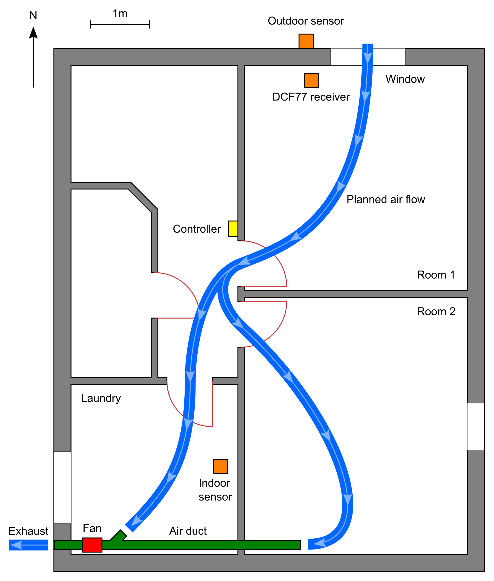
This is a floor plan of our basement. The total area is about 55 m². There are three rooms to be dehumidified (“Room 1”, “Room 2”, “Laundry”). In order to minimize effort, one single fan is installed in the laundry, which draws air from two rooms via an air duct. The air enters in the third room (Room 1) through the window so that fresh air is routed through all three rooms and the corridor.
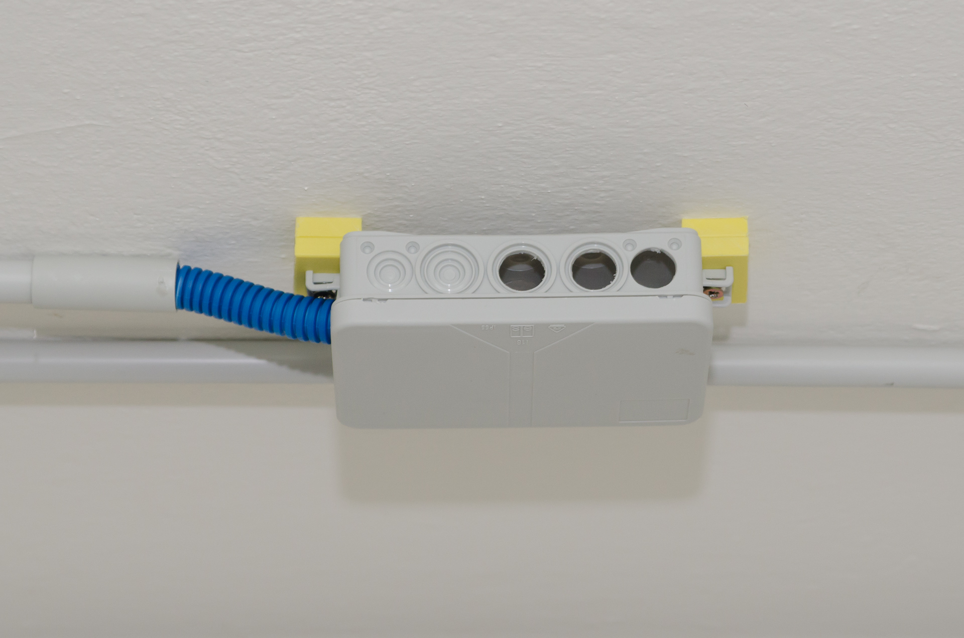
The controller
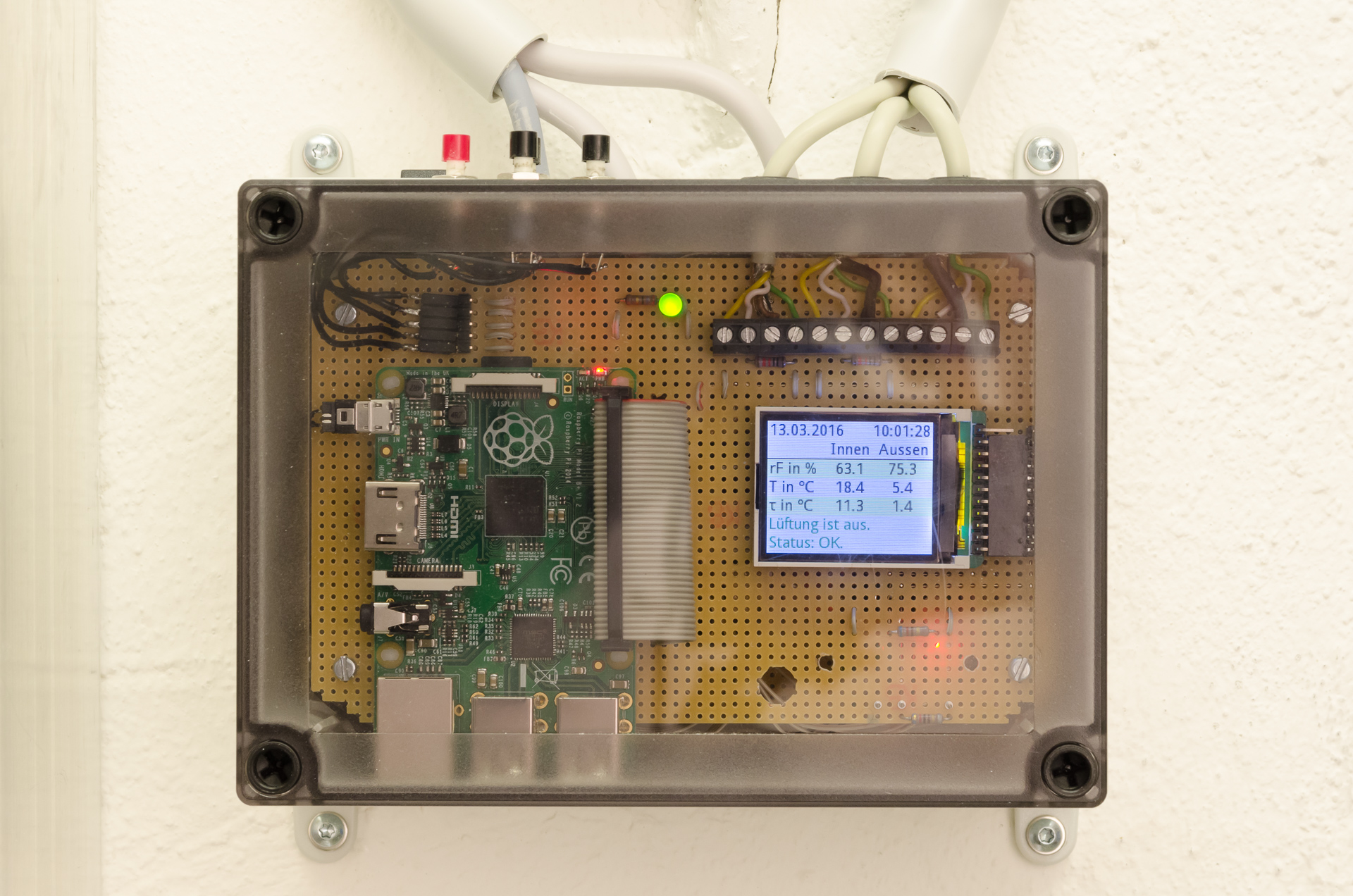
The controller is built around a Raspberry Pi. The case contains the power supply, the computer, a small display, relays for the fan and window motor, and buttons for user control. Since the Raspberry Pi has suitable input/output ports, little additional circuitry is needed—mostly wiring.
The sensors
The humidity sensors are two high-

Each sensor is encased in a sinter filter against dust:
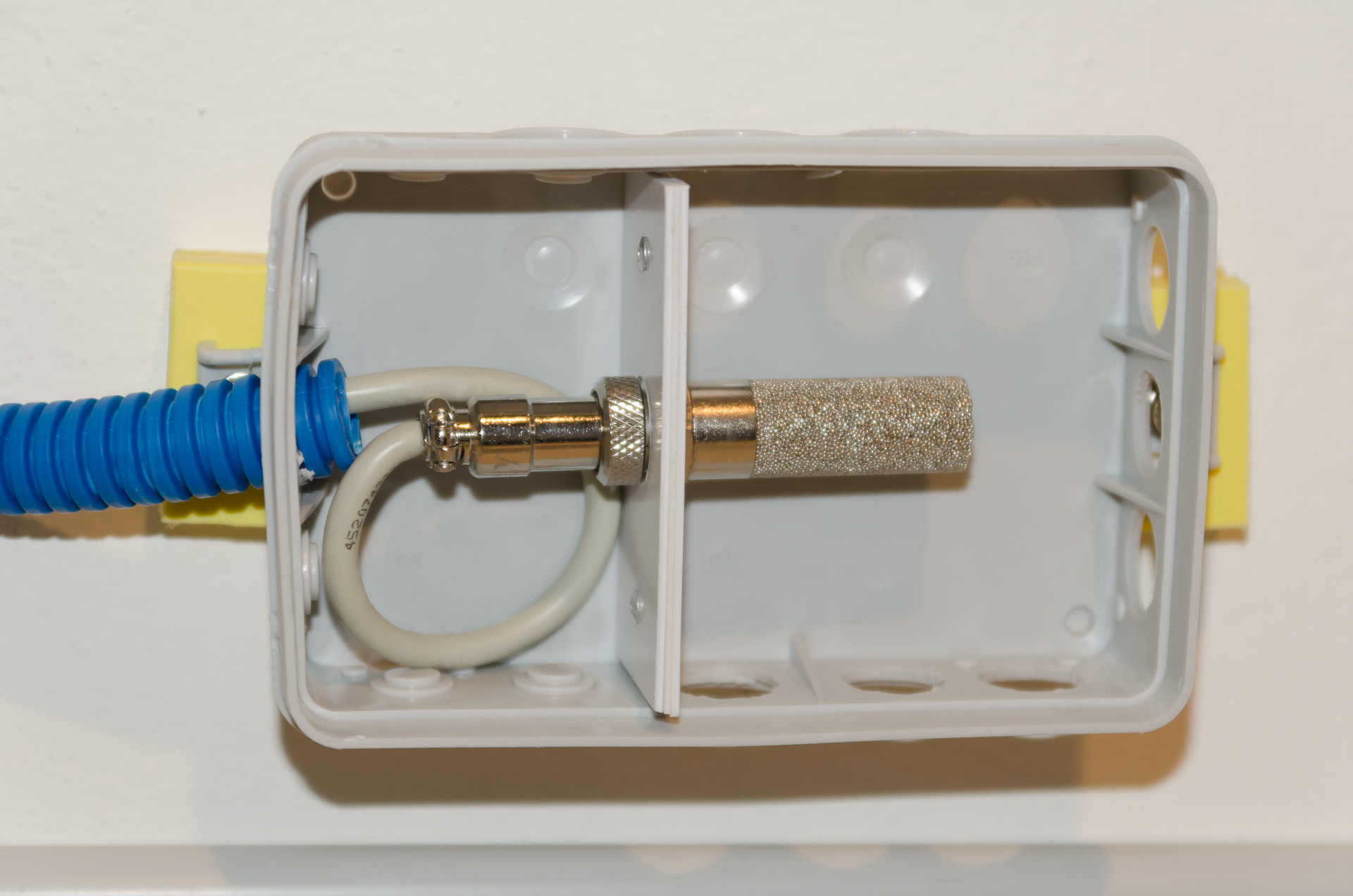
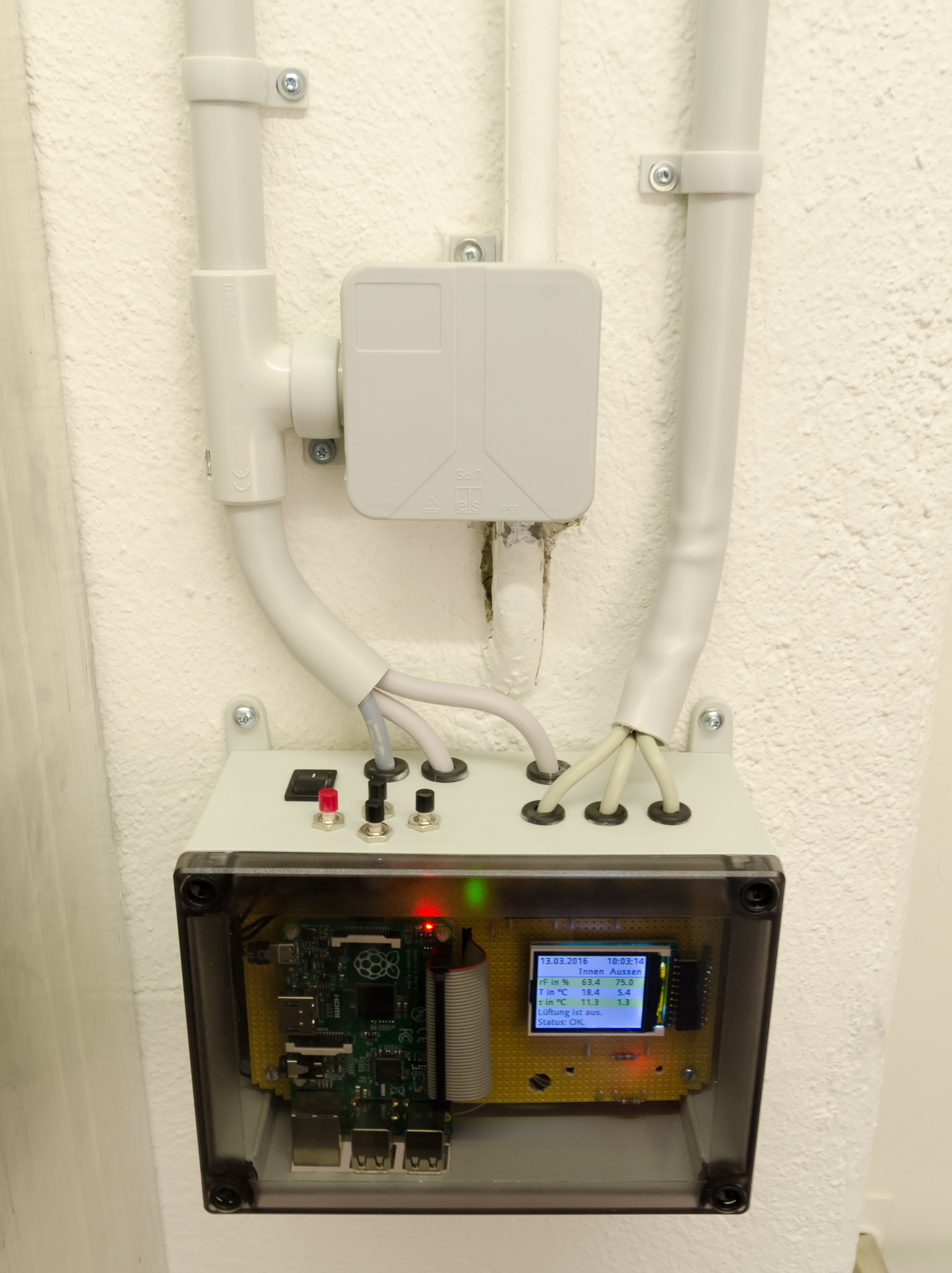
The unit is then mounted in a plastic case with holes to protect the sensors from rain and mechanical damage:
Here is the mounted outdoor sensor:

The fan
There is a single fan which moves all air. In order to vent the entire basement, the fan draws air both from the laundry and through an air duct from the adjacent storage room. The fan is a Vortice Lineo 150 V0. The photo below shows the installation in the laundry.

Below is a closeup of the fan with the laundry inlet. The aperture of the inlet valve can—in principle—be adjusted to distribute the air flow evenly between the two inlets. Since I do not have any means to measure air flow exactly, the valve is left wide open since there is an adequate air stream at both inlets in this configuration.

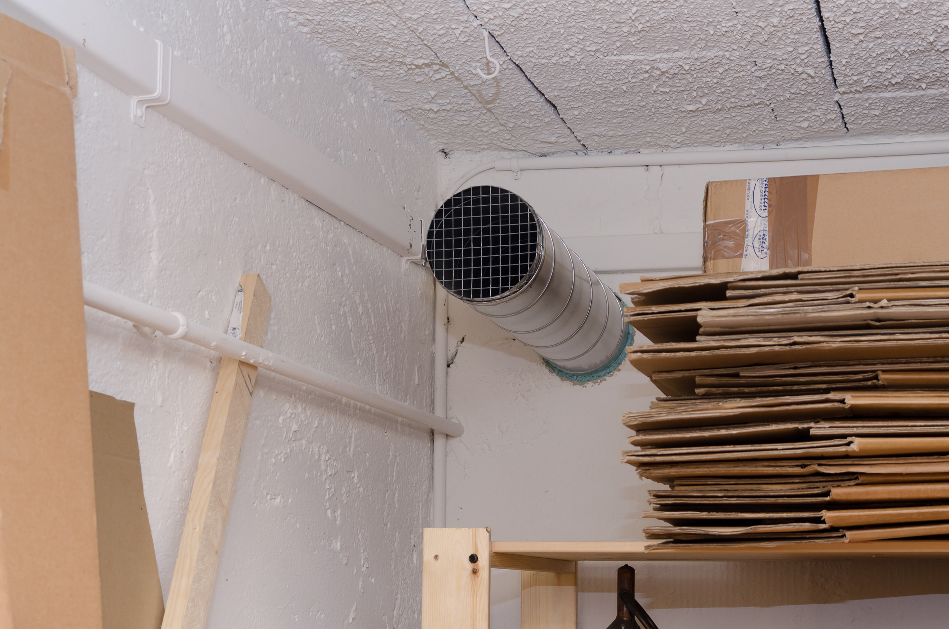
Air duct
There is a single, straight air duct across two rooms to outside. The diameter is 150 mm. See the pictures above for the part in the laundry. The hole in the wall was cut with a core drill. We had this step done by a mason. For the adventurous, core drills can also be rented (eg. at Bauhaus in Switzerland and Germany). The opening in the storage room is protected with a piece of wire fence.
Outlet
The laundry also got a new wall opening to outside. Here, we have an outlet with shutter to prevent wind from blowing into the basement and animals from entering when the fan is off. (There is also a check valve inside the tube between fan and outlet to seal the opening even better. I am not sure whether it is necessary.)

Intake
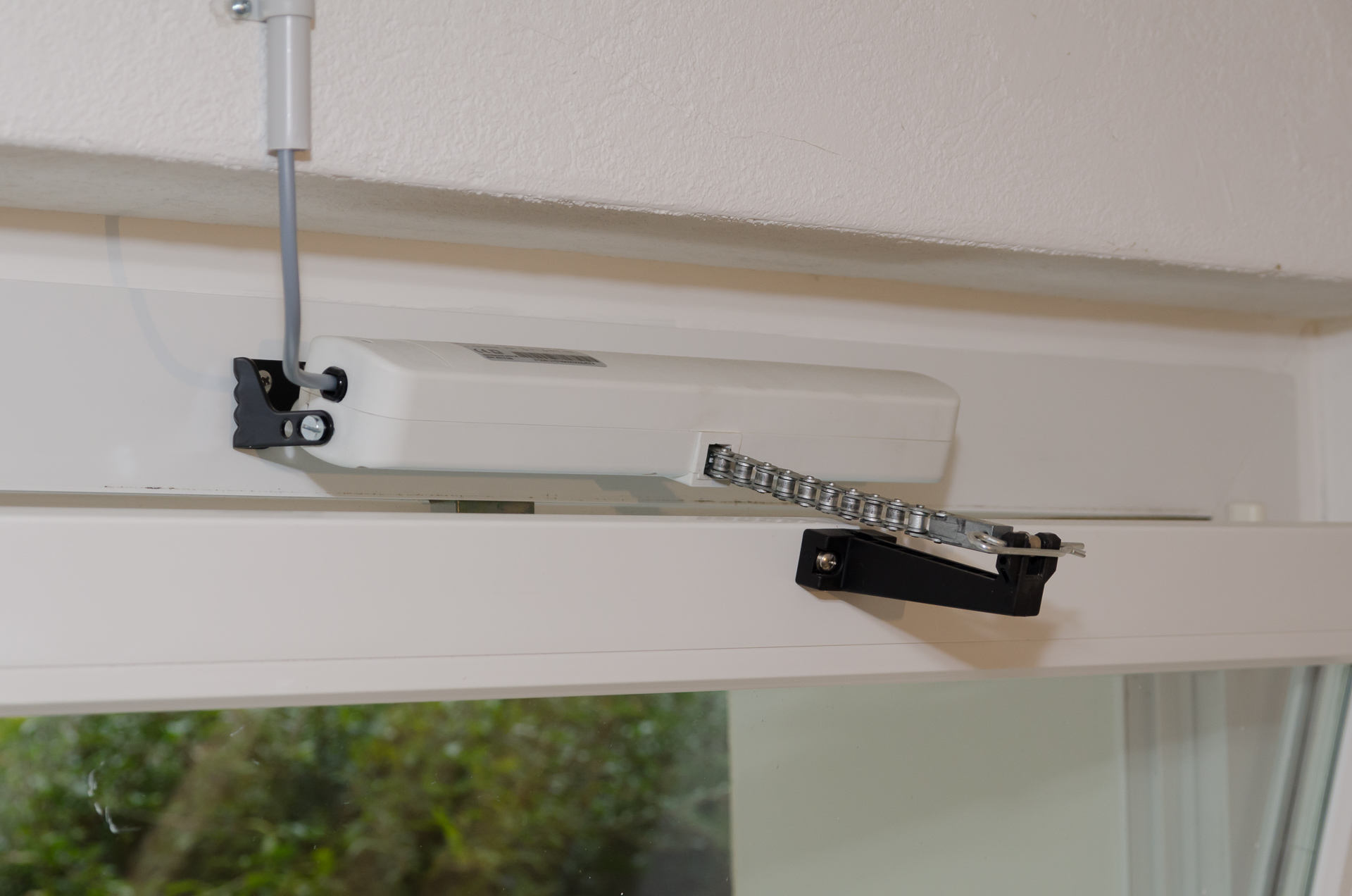
The window in the third basement room serves as the intake. I backfitted a motor to open and close it automatically.

The picture below shows a closeup of the motor when the window is open. The motor is a Mingardi Linea Micro KIT. Important criteria were that it works with narrow windows (note the pivoted mounting to accommodate the window's small tilting radius) and has adjustable stroke so that it does not damage the window frame. Other factors like noise, design or size of the motor were unimportant for a basement window.
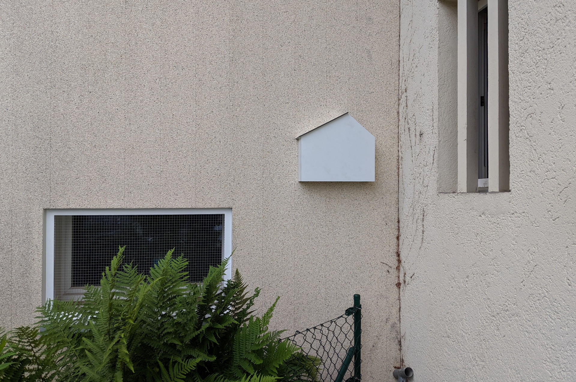
The intake window is on the north face of the building. The outdoor sensor is mounted in proximity to the intake, somewhat above the ground, and partially sheltered from rain by the eaves of the neighboring house. I installed a wire mesh in front of the window so that animals cannot enter the house or get trapped in the tilted window.
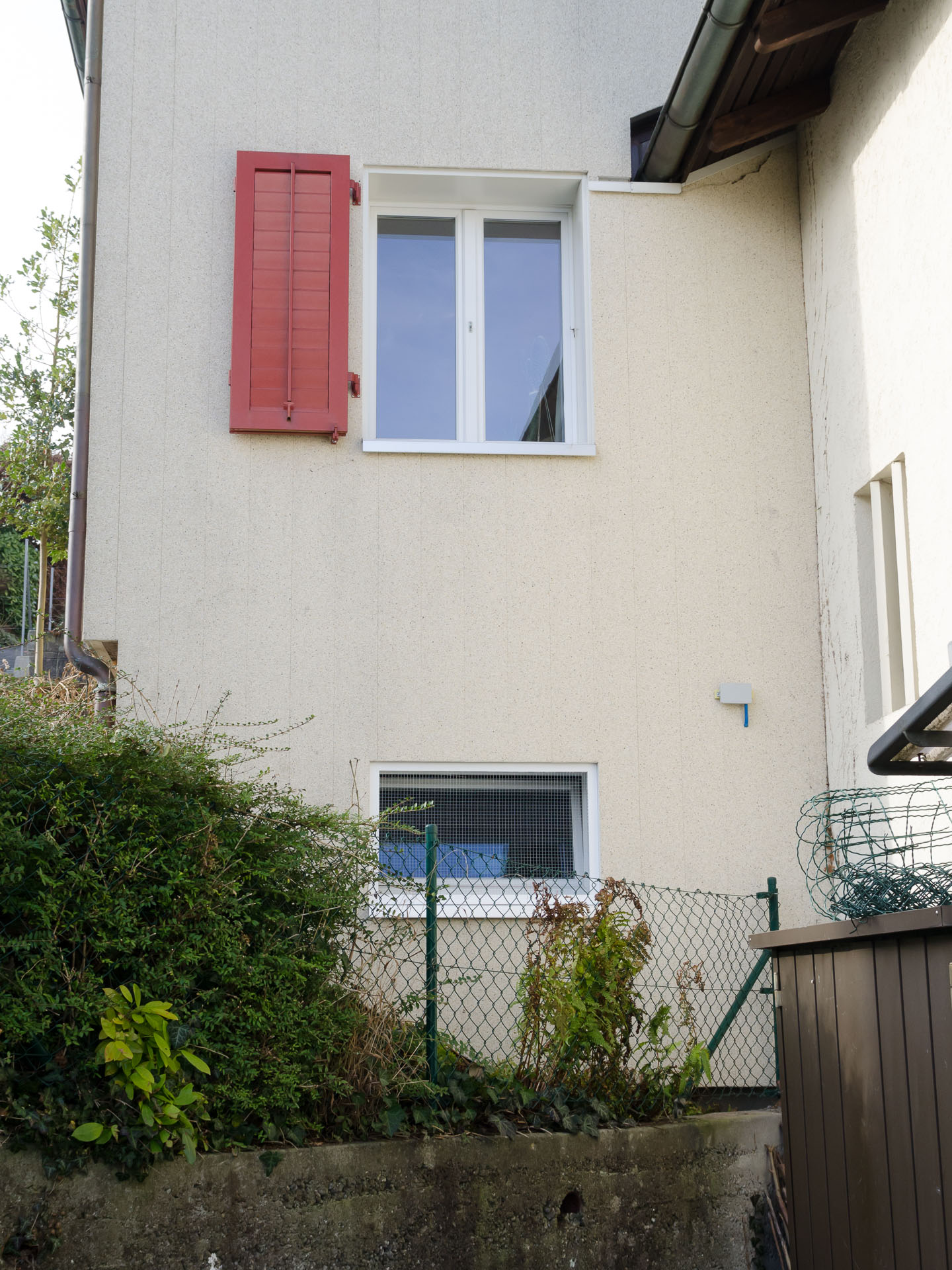
Even though the sensor is on the north face, it received direct sunlight during morning hours in summer, which heated the sensor up and distorted the measurements. I later added an extra housing made of high pressure laminate (HPL) to always keep the sensor in the shadow.

Radio clock receiver
I also installed a DCF77 time signal receiver. This part is optional since the controller in its current setting does not need to know the time of the day for proper function. I use the time signal only for correct logging timestamps, even without network connectivity. The receiver is from Conrad Electronics.

Network connectivity
Even though the controller is designed to work as a self-
3 The controller: hardware
The heart of the controller is a Raspberry Pi 1 Model B+. It has a single core CPU, which is enough for the task at hand, and consumes slightly less power than the quad-
The power supply is a small switching power supply (5 V, 2 A). These modules are sold for a few dollars at ebay and shipped from Hong Kong. Another part which is mass-
All components fit onto two Eurocards (ie., 160×100 mm circuit boards) and are stacked in a wall-

In front of this is the low-

The display is a small color LCD screen: SainSmart 1.8 ST7735R TFT LCD Module. It does not have any screw holes or other provisions for mounting, so it is simply held in place by its pin header.
Here is a picture of the controller case from above in its final state, with all cables installed:
The rear row are the 230V cables (power, fan, window motor) and the front row the low-
I plan to draw the circuit plan when I have time and publish it here.
4 The controller: software
The Raspberry Pi runs Arch Linux as its operating system. The controller software is entirely written in Python. Even though the software is written for this specific project, it has a completely modular structure, so that it can be adapted to other projects. Each module has a single responsibility (eg. taking measurements, display, logging, DCF77 time signal, user controls, deciding when to vent, driving the relays), so modules can be modified, moved or added easily. The central instance is a “message board”, over which every module posts, subscribes to, and queries information.
The controller software is published on GitHub: dmuellner/fancontrol. See there for further documentation.
I also describe a few details of the setup on a separate page.
Measurements
Humidity measurements are taken every 10 seconds. In general, a Raspberry Pi with a Linux operating system does not provide any straightforward options for real-
Algorithm
I experimented with a few algorithms to get the best performance in all seasons. There are two aspects to consider: First, ventilation should happen when the outside dew point is lower than the inside dew point. However, we do not want to permanently blow cold air into the house even if it is dry. The current rules are the following (slightly simplified):
- If the outside dew point is higher than inside, do not vent.
- Otherwise, if the outside temperature is at least 15 ℃, ventilate permanently.
- Otherwise, ventilate for 20 minutes, then make a break depending on outside temperature: the colder it is, the longer the break.
5 Results: sensor data
Sensor data is available from April 2016 to July 2019. Check the graphs page for different days to see how the controller behaves over the seasons.
6 Building your own ventilation system
To build such a system is more than just a weekend project. also, every house is different, so my description can only provide hints for an individual implementation.
There are also commercial product available:
- Ramser Elektrotechnik has a controller that apparently provides fine-grained configuration options.
- Schwille Elektronik sells a controller and fans.
Here are instructions for a similar DIY project: ArDewpoint.
Fans
One aspect for dimensioning a fan is obviously the flow rate. Note that the maximum throughput (eg., 500 m³/h) is only achieved if there is no flow resistance. If there is a pressure difference, the flow rate drops more or less quickly, depending on the type of fan. The fan specs always show these diagrams (flow rate depending on pressure difference). The way to go here is to make up your mind what throughput you want, plan the airways, ask an expert how much pressure difference is roughly to be expected and then dimension the fan (and maybe air ducts) accordingly.
If one fan cannot generate enough pressure or enough air flow, think about a push-
Sources
These are the experts who helped me:
- The ventilation equipment (fan, ducts etc.) was obtained from Anson AG in Zürich. They competently assisted in planning and dimensioning the ventilation and helped choosing the right fan.
- The window motor was purchased from Windowdrives in Germany. They have an excellent phone consulting service, a wide selection of window motors, and ship to all European countries.
-
The wall openings were drilled professionally by mason Michael Brugger (Flex-
Bau ).
Improvements
The next step in making the dehumidification even more energy-
Two small things could be improved about the controller hardware if I built it again:
- The user control buttons exhibit rather long contact bounce. This is dealt with in software at the expense of being not so snappy. It may be good to add hardware debouncing for the buttons.
-
When the controller is switched on, the switching power supply fills its capacitors nearly instantly with high current. Due to nuisance blows, I had to replace the fuse that I had dimensioned for normal operation (40 mA slow-
acting) by one with a much higher rated current (160 mA slow- acting) than necessary during continuous operation. If the switch- on current was restricted, one could opt for the safest version and could have a fast- acting fuse with low rated current.
Raspberry setup
Specific tips for setting up the software components on a Raspberry Pi with Arch Linux are written down on a separate page.